David A. Antler
3 things I learned about rotary encoders
Earlier this year I joined a volunteer group to help teach middle school students about electronics. Our team is furnishing a community center with hardware like the Arduino 101 and a couple of different types of Grove kits. We hoped that they could take these parts and build something of their own. Unfortunately the quadrature rotary encoder that came in a Grove Environment kit included a library which did not work with the Arduino 101, so I spent an afternoon writing a driver/library to support it. Here are some things I learned in the process.
Basics
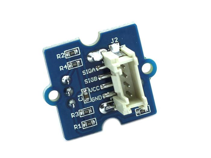
The pinout of the rotary encoder looks like this:

- D0 (least significant bit of binary output)
- D1 (most significant bit of binary output)
- Power
- Ground
What I got wrong
Having never used an encoder, but after seeing them around, I had always assumed that D0 and D1 would represent a binary number, and that a clockwise rotation would increment the number (until rolling over and dropping the top bit).
1 | # In decimal, clockwise rotation |
*each comma represents a “click” on the encoder
In the speculative and imaginary example above, the wheel will click for each comma, or 8 times, to get back to 0. Of course a counterclockwise rotation would do this same sequence, except backwards. How could a device be any simpler?
What I learned
There are three things wrong with my assumptions above, and I’ll explain what I learned!
1. Order matters
First of all, the order of clockwise encoding doesn’t increment additively! Here’s a corrected sequence below:
1 | # In decimal, clockwise rotation |
The rotary encoder will usually use a Gray code. Essentially the idea is to make only one wire of the binary output (D0, D1) change at a time.
The strange-looking gray code sequence may seem like a nightmare invented to make your code more difficult to write, but it’s actually quite helpful. For instance, if I hooked up an interrupt to both D0 and D1 and rotated the knob clockwise, that interrupt will actually trigger fewer times with an encoder that uses a gray code! This is because the transitions on an additive encoder (from 1->2 and 3->0) would both cause two interrupts due to the binary representation of those numbers! Grey code encoding successfully avoids those transitions.
2. Clicks aren’t a single step
I wired up my Arduino and naively wrote a sketch to read D0 and D1 every 100 milliseconds and print it to the screen. My serial output told me “3”. Great!
I turned the knob once, expecting to see another number like 0 or 2. Nope. “3”!
I turned it again. “3”. Again! “3”!
Now I’m turning the knob furiously, and I see a bunch of numbers, but as soon as I stop turning, back to 3. Hmm.
I realized that between each click of the wheel, I was actually cycling from 3, through all the numbers, and then back to 3! Allow me to correct my comma usage from before…
1 | # In decimal, clockwise rotation |
*each comma represents a “click” on the encoder. Note that there are only two commas in this corrected sequence!
3. Encoders don’t actually ‘click’
A final source of my confusion was actually the data sheet. Nowhere will you see the word “click” on a rotary encoder datasheet. But surely some information about the “click” needs to be a documented mechanical aspect of the device. For instance; how many clicks are in a full rotation?
Unfortunately I suppose datasheet authors decided the word “click” is an onomonopia, and how unprofessional would it be to use one of those in an engineering document?!?
The proper word is actually “detent.” One “detent” is one click. I hope this helps you in your Googling!
Final notes
The Grove v1.2 encoder had the following properties:
- At-rest state count:
1 - At-rest state values:
[3] - Transitions per detent:
4 - Rotation encoding:
"Gray"
You could imagine that different encoders exist with different values for each of the properties above.