David A. Antler
World's smartest MUJI diffuser
Usually I’m great at resisting the urge to buy tchotchkes. My minimalist resolve is put to the test when I get the chance to enter a Muji store.
In case you’ve not yet heard of it, Muji is a company that’s kind of like an upscale Japanese IKEA. They have a universe of basic products that are well designed and good value.
On my last pilgrimage to Muji, they had a sale on their neato ultrasonic diffuser. It’s a small appliance that vibrates in just the right way to expel a stream of cool mist up into the air. You can add what I’m learning are called “essential oils” to the internal water reservoir to make the vapor have a pleasant aroma. On top of that, it also produces a diffuse light. Overall it’s an aesthetic item with some calming properties.
But I’m accustomed to things being automatic in my life. I hit buttons for a living at work all day so, in the spirit of work-life balance, I try to avoid hitting buttons at home. Unfortunately buttons are the only way Muji wants me to control the device.
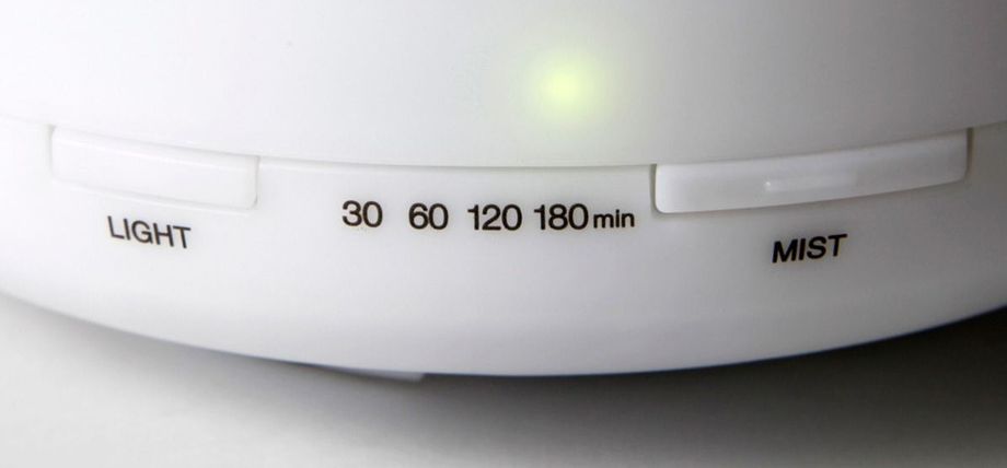
This is, of course, a major problem. But what’s a problem but something to throw time and money at?
My goal with this project is to control this ordinary diffuser with my iPhone, using Siri and the Home app.
Design and engineering
Upgrading this diffuser device involves solving problems in the domain of mechanical design, electrical engineering, and software development. My general idea was to have the device look and work exactly as it does originally, but to also hide some additional components on the inside.
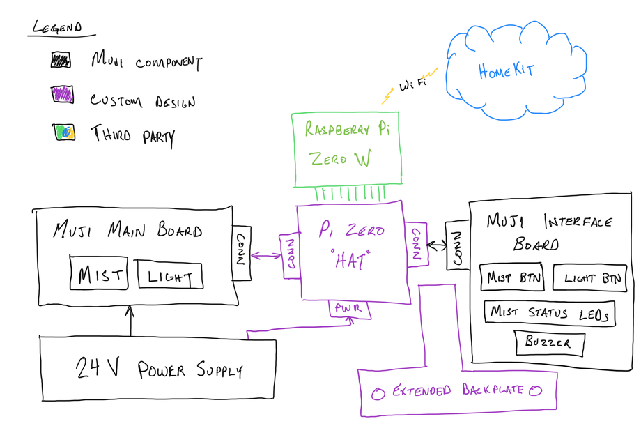
I could accomplish this by stealing power from the standard power supply and squeeze some extra trickery between the interface board and the main board. The overall system I decided to build looks like this:
Mechanical
The first problem to solve is mechanical. I need to fit some custom hardware and a small computer into the enclosure.
I found out during my earlier teardown that the interface board was attached to a small plastic part. Conveniently this part happens to feature a cavity which is the perfect width to sneak in a Raspberry Pi Zero. I could basically clone this design, but extend the top of it slightly, to make a place to attach my Pi. I took some careful measurements of the existing part and designed a new mounting plate using FreeCAD that could be 3D printed.
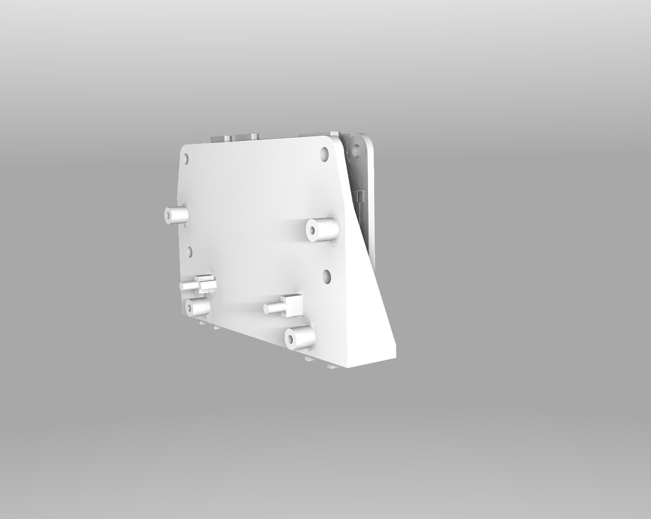
The Pi looks quite snug in there. But overall this is promising.
Electronics
The electrical engineering challenge is in the support circuitry. This circuitry is designed to solve four problems:
- Provide power to the Pi
- Provide a method of virtually “pressing” the Light and Mist buttons
- Support the ability to read the state of the mist time LEDs.
- Provide a method of measuring the internal light level.
In addition, I designed it so that the buttons still work as normal when pressed (in case the Pi crashes or the network goes down).
Power
Power gets regulated down from 24V to 5V for the Pi using a Texas Instruments LM2674MX chip, and the full BOM came from their excellent WEBENCH tool. I measured the power consumption of my additional components to be about 0.75 watts, so I chose a 2.5 watt supply to provide plenty of headroom.
Virtual button presses
Designing a circuit to “push” the button via the Pi was a bit less straightforward. The voltage differential is 5V as measured across the un-pressed button, but the positive terminal is held at 24V relative to the Pi’s ground. I used my DMM in current mode to short the button and noticed that only 2.5 mA was required to turn on the light. In order to create a 2.5 mA current from a 24V rail to a 19V rail, I decided to use an optoisolator. I found a chip called an ILD213T that meets these requirements when driven with an ordinary Pi GPIO pin through a 330 ohm resistor. Problem solved!
Reading mist status LEDs
Reading the status of the mist LEDs is a similar challenge due to a large voltage differential from Pi’s ground. In the off state, the LED-driving pins sit at 19V above Pi ground. If the LED is on, then the pins will be closer to 21.5V. However, the Pi can only safely read from 0V to 3.6V on its GPIO pins. I ended up using a zener diode with a 18V breakdown voltage as well as a silicon diode and a resistor to step down the voltage to the proper level to be read with the Pi.
Measuring internal light level
Finally, to measure the internal light level, I decided to include an ambient light sensor IC. I found a chip called a VEML7700 (mostly chosen because it looked possible to hand-solder) and put it in an area where I thought it would be able to see some light.
Making it fit.
Solving these problems presents another mechanical challenge to overcome. How can I make it fit? I decided to design it similar to other Raspberry Pi expansion boards, sometimes called a Pi Hat. Here’s the board I designed in KiCAD which sneakily fits a 7-pin header midway through the normal spot where 40 pin Pi Hat connectors live.
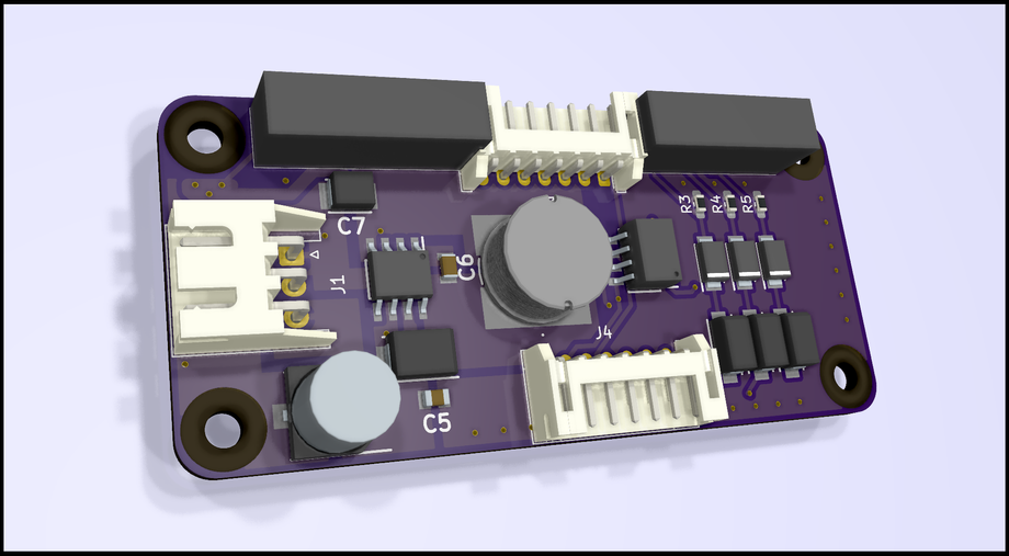
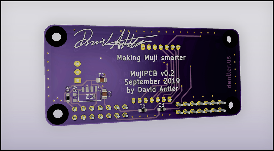
The above renders are pretty, but it needs to fit the overall system. Imported into FreeCAD with the backplate, my Pi Hat looks like this:
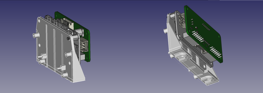
After a few spins, it seems likely to fit with the Pi on my new mounting plate. Now it’s time to buy everything.
The electrical BOM turned out to be quite expensive at around $60. Each PCB is $10 from OSH Park. The Pi Zero W with SD Card is $17.50. Miscellaneous cables, chips, connectors, stand-offs, and passives are probably another $25. But this is acceptable for a one-of-a-kind design.
Software
The software is the final piece. I decided to use Raspbian Lite to get the system up and running quickly with Linux and a wireless networking stack. Some custom software had to be written as well.
My other smart home gadgets use HomeKit, so I’ve become accustomed to using Siri to command my devices. I found a simple library on GitHub called HAP-NodeJS which allows me to expose my Pi as a “Bridge” that hosts two HomeKit devices:
- A lightbulb, which can expose the lighting and brightness capability of the device.
- An outlet, which can expose the misting capability of the device.
HomeKit may issue commands or request the status of these devices, and it is my software’s job to service them.
One possible command is “turn on the light.” In the simplest case, such a command from HomeKit can be serviced by emulating a physical button press on the “Light” button using my aforementioned optoisolator circuit. Hooray!
Status monitoring commands can be a bit trickier to handle. If HomeKit asks, “Is the mist function on?”, then I can easily read the status of the green LEDs to determine if the mist is running. However, if HomeKit asks, “Is the light bulb on?” then the answer is not so simple. The status of the lighting is not exposed on any electrical connectors, so I had to get creative.
Calibrating the ambient light sensor
Since there isn’t a non-intrusive way of directly monitoring the status of the device’s internal lamp, I decided to embed an Ambient Light Sensor (ALS) device to try and see if I could sense the lamp’s status.
My first experiment was to try manually querying the ALS for brightness with the lamp at all three settings { OFF, LOW, HIGH } and hard-coding their midpoints as threshold values. Here’s my lab notebook:
1 | Measured values: |
After computing these values, I can now read the ALS and—depending on its value relative to these thresholds—determine the status of the internal light. For instance, a value of 92 is between the two thresholds, which means the light must be in a LOW state.
Unfortunately I wrote this code at night, and it stopped working when morning rolled around. The ALS was only reading values above 200!
What worked better was implementing an online calibration routine. This routine basically just automates the first procedure I tried in my lab notebook. Software repeatedly “presses” the lamp button (using the optoisolator circuit) and measures the brightness detected on the ALS until it has 3 distinct values. A distinct value is one whose value is a distance of at least 12 away from any prior number. These values are sorted and then their midpoints are used as the new computed thresholds.
My online calibration seems to work, but calibration needs to run several times per day. It’s actually kind of fun to watch the light come on all by itself and cycle through its modes.
Build and installation
In building this system, my goal was to not destroy any of the original components from Muji. This is challenging because the body of the device, including all of the threaded holes, are plastic and easily stripped. Also the electrical connectors are not rated for too many insertions, so I can’t perform too many experiments without breaking the device!
Modifying Muji’s components
The first thing to modify is the power cable’s barrel jack input, since I need the 24V to power the Pi. Removing some screws gave me access to a thru-hole barrel connector that looks like this:
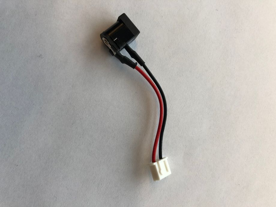
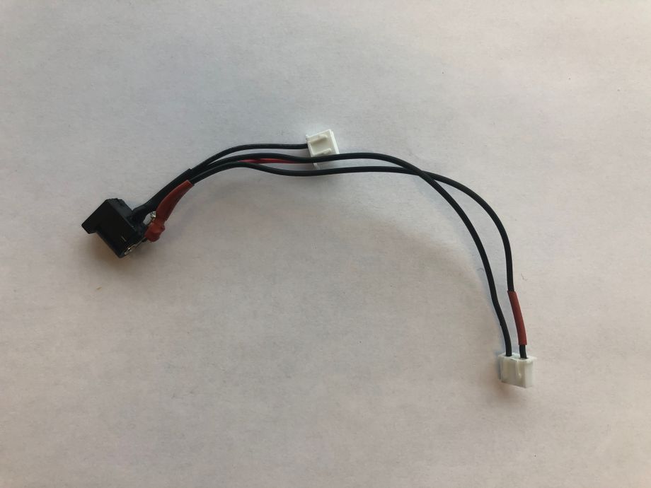
I had to cut the original shrink wrap, de-solder the wires, and then pull in some extra pre-crimped wires and re-solder them back onto their proper terminals. I was able to locate the exact connector that Muji used on DigiKey so I decided to make it pin compatible.
Building the new interface board
I ordered my printed circuit board (PCB) from OSH Park. It looked just like the render but I had to get all the components on it.
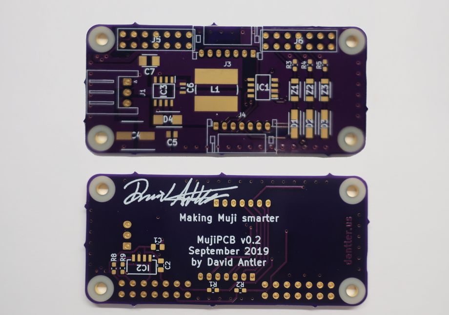
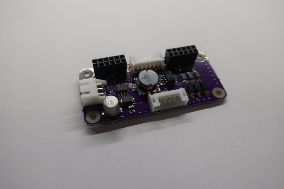
After a bit of soldering and several issues identifying pin #1, I was able to piece the thing together.
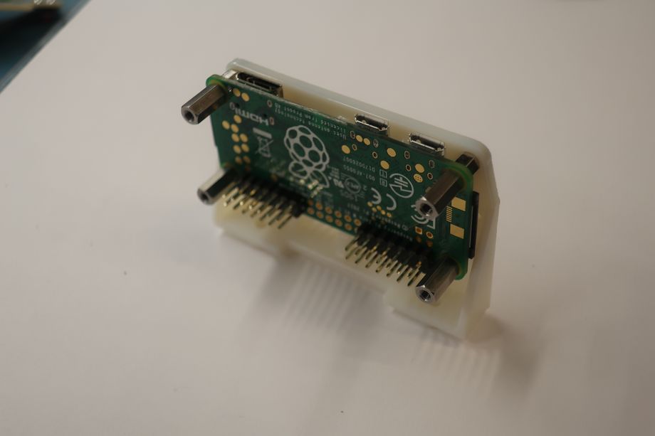
The next thing to do was to start building up the new backplate. First I needed to attach the Raspberry Pi to the 3D printed backplate via some 5 mm standoffs and M2.5 screws.
Next I had to attach Muji’s original interface PCB and screw it into the 3D printed backplate as well. This thankfully just worked, using the original screws and without printing any special threads into the material. The secret is to add 0.15mm extra tolerance to the inner diameter of the holes, which made the screws thread snugly into the material.
It took me a fair amount of fiddling to fit the rest of this together, which you can read about in the source of this site (if you’re so inclined).
After enough fiddling was completed, the build looked good enough for me:
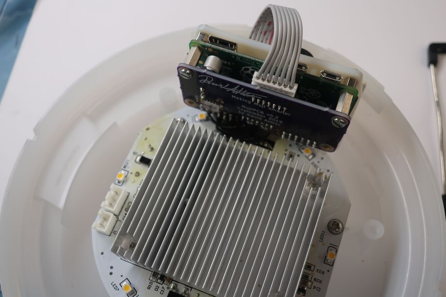
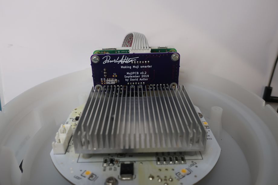
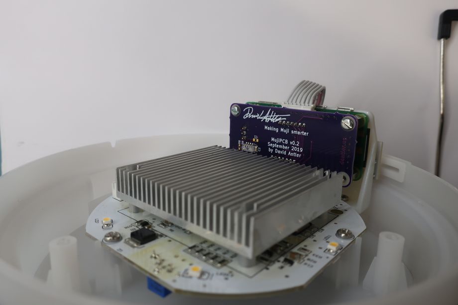
I plugged in the power, screwed the bottom back on, and it’s basically complete!
Mistakes and errata
One issue I didn’t anticipate was the full mechanical consequence of adding a little extra height to the original backplate. Although my 3D printed plate does fit into the Z-height of the enclosure, there were some small “+” shaped extrusions that smash right into my standoffs which hold the Raspberry Pi to the plate. Unfortunately I had to make a destructive modification here and snip these extrusions off completely.
One other mechanical concern I forgot to account for was the thickness of the wires running from Muji’s button board to my custom Pi Hat. These wires run right over the already-snug backplate. Even after a tiny bit of sanding, it was too snug. The added thickness from these wires unfortunately prevent the device from perfectly closing up, and there’s a bit of a misalignment.
Perhaps you also noticed that the board says v0.2 and are wondering what happened to v0.1. Unfortunately I made an error in the schematic that was impossible to fix cleanly, so I rev’d the board. I took the opportunity to switch to a new voltage regulator which uses 7 times more components, but is overall less expensive, more efficient, and has a shorter z-height.
Overall thoughts and demo
I’m satisfied with the results of this project. This device fits well into a nook of my apartment which was previously dark, but is now automatically (and aromatically) illuminated by HomeKit automation. The system is stable and I haven’t noticed any downtime. The device went from rare use to a daily part of my life so I’d say this “upgrade” was worth the price. Hopefully Muji will consider adding something like this to their product portfolio soon!
Here’s a video of it in action. Siri’s voice is a little faint, but you can hear her speaking.